Scalar Altimeter

As a part of my “Otter Space” project with a friend, where we are developing avionics components for hobby rocketry, we set out to create one of the smallest dual-deploy altimeters on the market. From that mission alone, we pulled the two main driving design requirements that would influence the hardware design: physical footptint should be as small as reasonably possible (without compromising on essentials such as mounting holes) and the altimeter must be capable of dual deployment (two independent pyro channels).
From there, I set out to create a preliminary hardware design for the system including component selection and overall system sizing. I started by defining the essential functional blocks of the altimeter: microcontroller, sensor(s), pryo channels, memory, power, indicators, and connectors.
The first block I focused on was sensors as this would drive requirements for the microcontroller in terms of IO requirements as well as computational requirements. Although some altimeters in the hobby rocketry space utilize multiple types of sensors to provide more accurate and higher-definition state estimates, the more sensors present in a system, the more space it requires. Since this project was fundamentally space-constrainted from the start, it made sense to settle on a barometric-only altimeter approach where the only sensor required is a barometer. Being limited to a single direct measurement (pressure, later converted to altitude) meant Scalar would only be able to determine a rocket’s altitude with the only possible addition being a calculated vertical velocity.
Previous designs have had success using the MS5611 barometer for rocketry applications as it has a resolution and absolute pressure range suitable for most high-power flights. From initial size estimates, the MS5611 seemed too large to fit with the rest of the required components so a smaller barometer was needed. At almost half the size of the MS5611 but with similar specs for this application, the MS5637 was an obvious choice. The only issue, it seemed, was that there weren’t any readily available breakout boards to test the sensor. I designed a simple breakout board for the MS5637 and prototyped it with a PCB laser to verify the performance of the sensor before integrating it into the altimeter design.
The next focus was on the pyro channels and connectors. To switch the high transient currents required to ignite e-matches, N-channel MOSFETs used as low-side switches are common and were chosen for this application. Specific MOSFET selection was a function of required switching voltages and current along with device footprint, availability, and efficiency (namely RDS,on). Similarly to the barometer, test breakout boards were created for the MOSFETs to validate their performance.
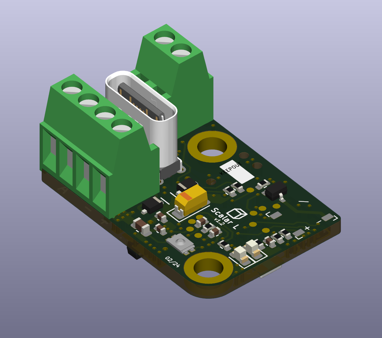
To connect the pyro channels to e-matches, various connector types were considered for their size, current capacity, and vibration resistance. Although slightly larger than desired, typical 0.1” pitch screw terminal blocks were selected for Scalar due to their prevalence in hobby rocketry and ease of use, requiring only a flathead screwdriver (no special crimp tools, or soldering). The terminal blocks (including those for power input) were placed around a vertical USB-C port for added mechanical stability.
Selection of indicators and memory was fairly uneventful, with the same considerations for performance and footprint as the barometer and pyro channels. Of note was the buzzer selection, which yielded a compact 3.3V buzzer and a similarly compact single-channel FET to drive it at higher currents than an IO pin.
With rest of the major components chosen for the project, focus shifted to sourcing a microcontroller. In previous altimeter and flight computer designs, I had utlitized SparkFun’s MicroMod line of processor boards, which abstracted away the intricacies of the microcontroller and its supporting circuitry and allowed the design to focus on the rest of the system. The size of the MicroMod processor boards alone immediately ruled them out from the design, as at 0.87” x 0.87” they were larger in at least one direction than the desired size for Scalar. As detailed on the MQP project page, I had hoped to use an STM32 microcontroller for Polaris 3 but was unable to because of SparkFun’s chosen implementation on their processor board. Now, however, without the MicroMod constraints I was free to explore the possibility of implementing an STM32.
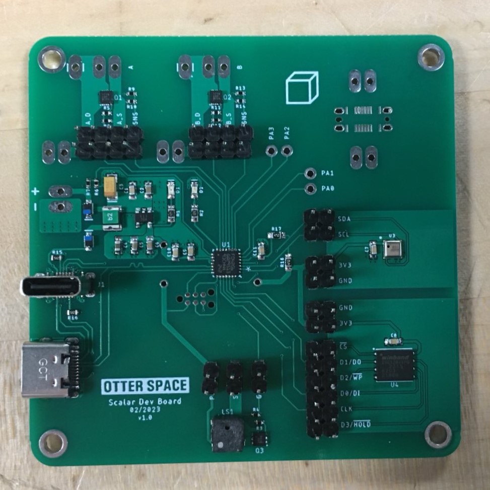
Initially, I considered controllers from the STM32 F line as they are relatively high-performance and considered to be a good starting point for rocketry/UAV applications. Quickly, though, I realized that the F line would be overkill for Scalar’s application and likely would exceed size and price targets. With that, lower-end STM microcontrollers were considered from both the STM8 and STM32 lines. Eventually, the design settled on a specific microcontroller STM32 L line which satisfied the IO, interface, and memory requirements while being available in a compact QFN32 footprint. Initial testing of the processor was done using a development board from ST, however efforts shifted to a custom dev board with the selected microcontroller as well as peripherals on a much larger board to allow for initial electrical testing and software work.

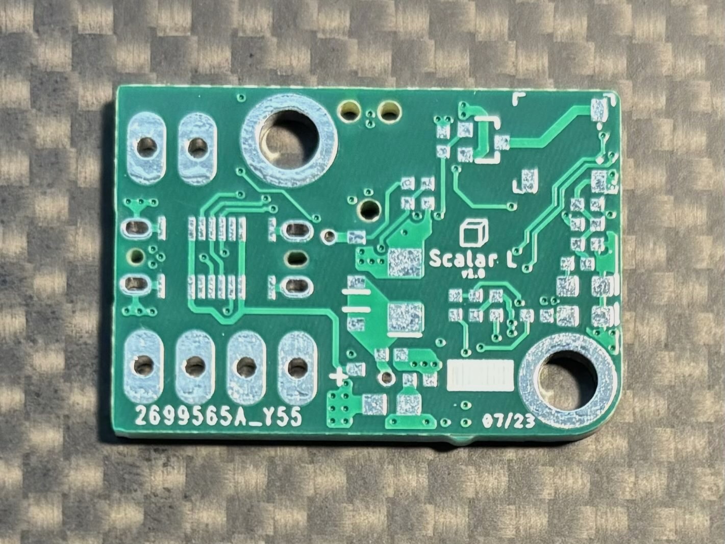
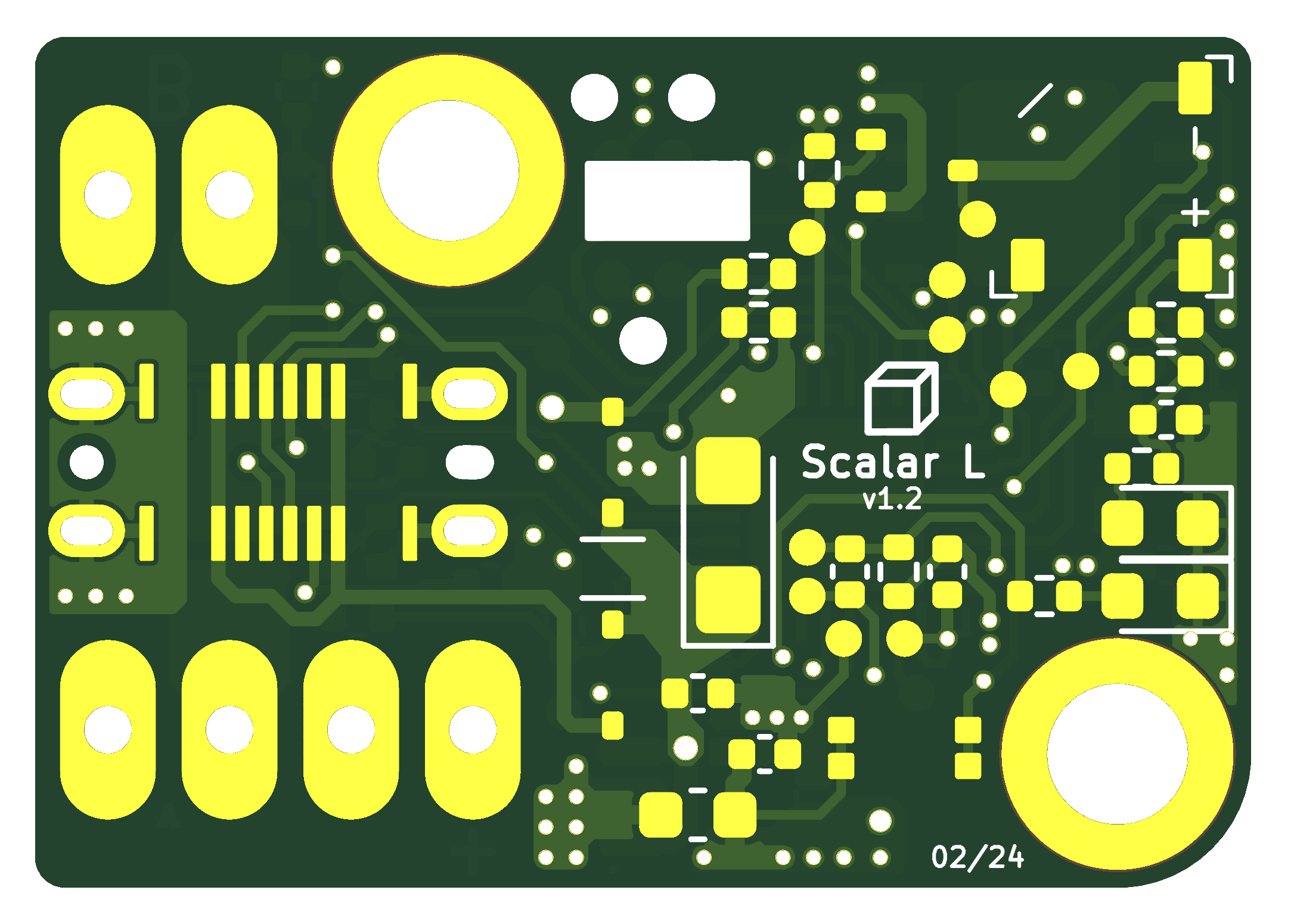
Once the development board was fully validated and any major issues were discovered, the focus shifted to KiCad for the flight board schematic capture and layout. The schematic capture was relatively straightforward, with the schematics being broken out into pages for each functional block and symbols created as necessary. To enable routing within the board’s small dimensions, the board was designed as a 4-layer board allowing ground and power planes to exist without physically interfering with signal routing.

Once boards were received from the manufacturer, one test board was assembled. Most systems worked immediately, however there was an issue with the flash chip occasionally not being detected by the microcontroller. Through troubleshooting the SPI communication between the flash and the microcontroller, an error was found in the schematic where the write protect and hold pins of the flash chip were not properly pulled high. Throughout the troubleshooting process, there was a distinct lack of accessible test points on the board to assist, so the next revision of the board included better test points as well as fixes to the issues found during bring up of the first revision.

Flight and interface software for Scalar are still currently being developed, so there has not yet been any flight testing of the altimeter.
04/2023 – Present