Switching PSU

In August 2022, I set out to design a DC-DC switching power supply to be used for powering rocket avionics and UAV peripherals. The scope of the project was to create a “Battery Eliminator Circuit” (BEC) allowing different configurations of Lithium Polymer (LiPo) batteries to be used to power 3.3V electronic systems, such as microcontrollers. Using specifications determined from requirements and constraints, schematic capture of the system was completed using Autodesk EAGLE. A general buck converter scheme was followed using the AP63356 switching controller from Diodes Incorporated. Component selection for supporting components and analysis is detailed in the full report which can be found below.

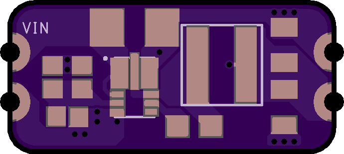
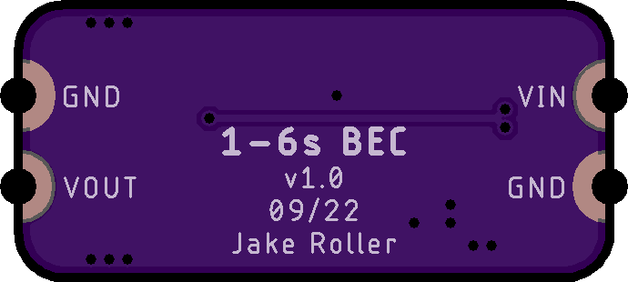
With the schematic capture completed, PCB layout was also completed using EAGLE. Special consideration was given to the layout of components to minimize distance between connected signals and to follow a logical pattern. Polygon pours were used in almost every case on this board to make electrical connections, allowing for higher-current carrying capacity when compared to traditional trace-based PCB routing methods.


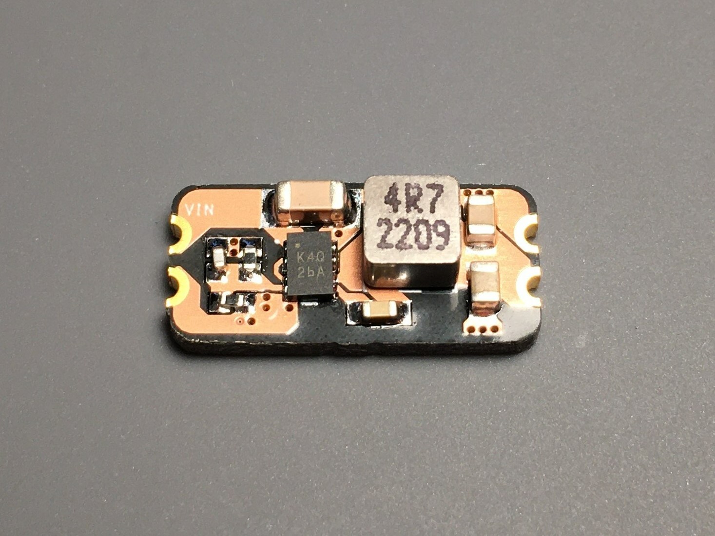
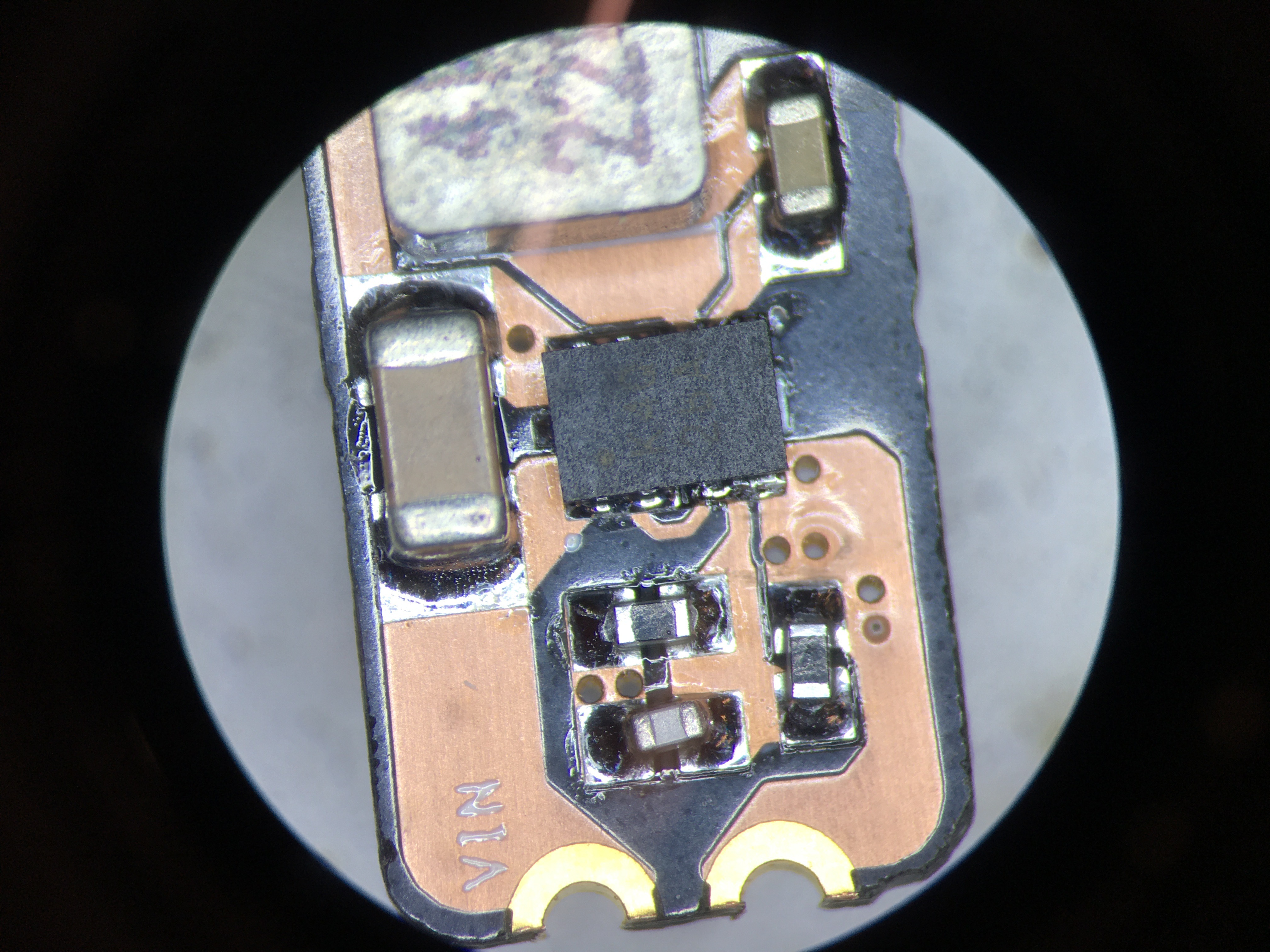
Boards were ordered from and fabricated by OSH Park. During manufacturing, an error occurred leaving only two of the nine boards ordered in a useable state and adding considerable delay to the project. Once the boards were received, though, a stencil was used to apply solder paste to the pads on the board. Components were then placed by hand according to the layout, and the solder was reflowed using a hot air workstation. Inspection of the fully assembled board revealed a few shorts on the switching controller pins that required manual rework with a precision soldering station.
Once the board was fully assembled and free of shorts, it was ready for test. Due to the significant delay added by the board fabrication, I couldn’t conduct many extensive tests and fully validate the system. Initial tests with a DC power supply as the input source led to only a 0.8 V output which is significantly under the required 3.3 V output. Interestingly, 0.8 V is the feedback voltage that the switching controller uses for its internal control loop. Because of this, the feedback voltage divider network was identified as a potential fault point. However, inspection of the network yielded the in-tolerance values when compared to the designed values. Due to the abbreviated testing conducted, many further tests are required to diagnose the issue with the system for future revisions. The first test that should be conducted in the future is to use an oscilloscope to observe the switching behavior of the system. By attaching a probe to the switching pad of the bootstrap capacitor, the switching output of the controller can be observed to determine if the controller is functioning properly. Additionally, the switching controller used contains a PG (power-good) pin that indicates whether the control senses a nominal operation state which could be another point for inspection, although this would require re-soldering the switching controller to add a probe wire underneath it.
There are many more measurements that could be done to further diagnose the faulty operation of the system, such as checking for proper soft-start and duty cycle. Once these tests are conducted, and the root cause of the issue is identified, a second revision of the power supply should be made. In this second revision, additional improvements could improve a second output rail at 5 V for powering actuators along with increasing the thermal mass of the board.
08/2022 – 10/2022
