HPR MQP
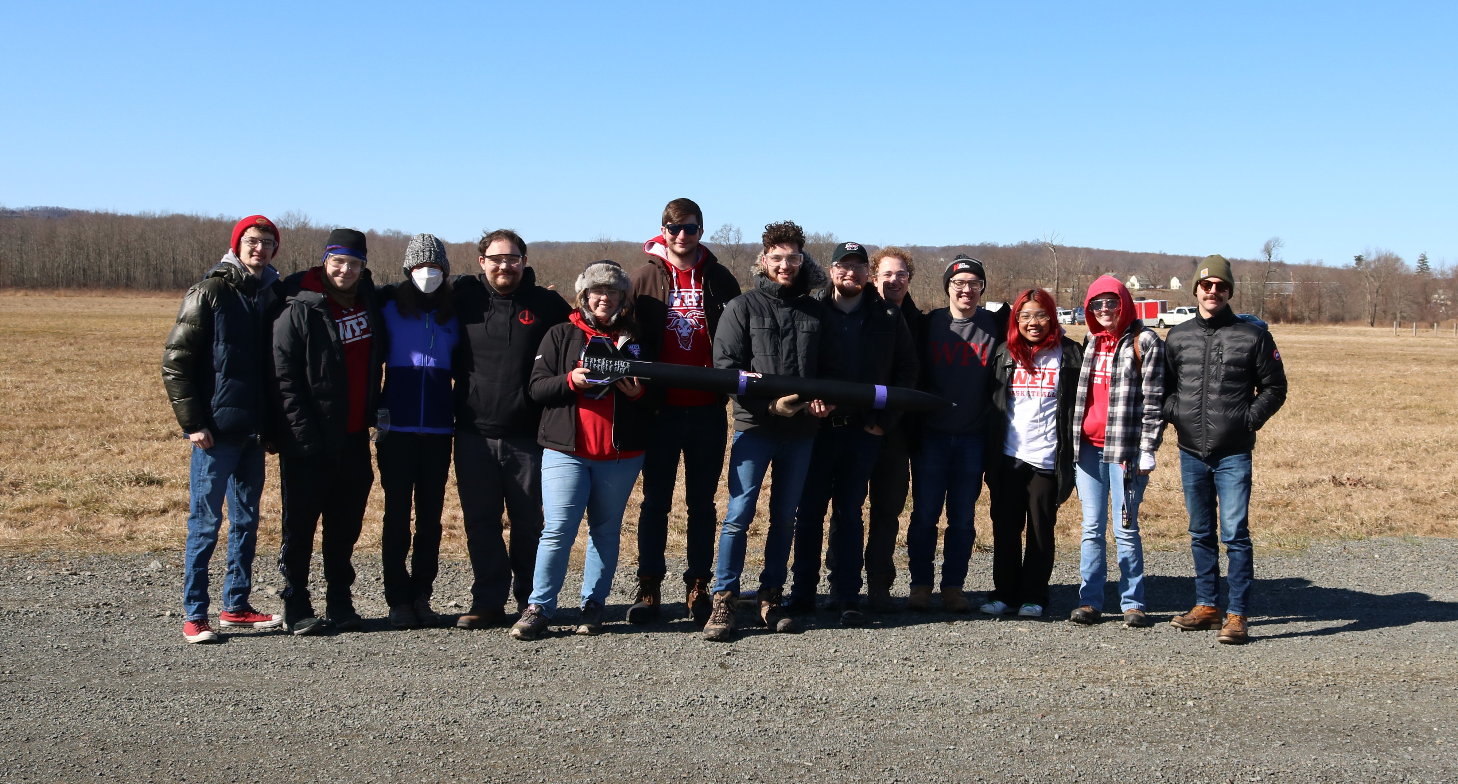
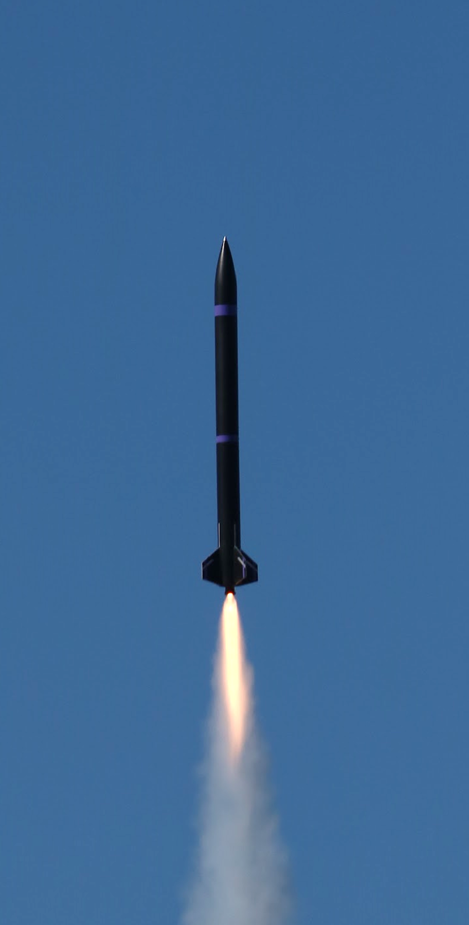
For my senior capstone project, or Major Qualifying Project (MQP) at WPI, I completed the design, analysis, and test of a reusable high-powered rocket together with a team of 11 peers. The team split into three subteams: Airframe and Recovery Systems (ARS), Flight Dynamics and Analysis (FDA), and Propulsion, Thermal, and Separation Systems (PTSS). I, along with 3 others, worked on the FDA Subteam, however I often found the team working cross-functionally amongst the Subteams to accomplish the shared goal.
As part of the FDA subteam, my primary tasking was to develop an avionics system to record data and control peripherals, as well as developing the embedded software that would run on the flight computer including a Kalman filter for state estimation. This page will focus primarily on the flight computer, however the detailed report for this project can be found below, or on WPI’s website.
Early on in the design process, the PTSS team decided on a servo-driven stage separation system to reduce the required turnaround time between recovery and re-launch. To reliably control this custom separation system, the launch vehicle required a flight computer capable of sensing and predicting the vehicle’s motion through space, as well as outputting pulse width modulation (PWM) signals while also firing pyrotechnic charges for the backup separation system. At the time, there were no commercially available altimeters capable of outputting PWM signals to control servos. To overcome the shortcomings of commercially available systems, the team decided to design and fabricate a custom flight computer according to the project’s requirements.
This flight computer was designed as a further iteration of the Polaris line of flight computers which I developed for HPRC (WPI’s rocketry team). As discussed in the development of Polaris 1 and 2, SparkFun’s line of MicroMod products contains a wide range of embedded processors, which are designed to fit into an M.2 connector while still providing the computational horsepower needed for predictive modeling and apogee detection. The initial microcontroller chosen was the STM32F405 housed on a MicroMod processor board. The STM32 is the industry standard for rocketry altimeters and UAV flight controllers however, upon testing the processor board, it was discovered that several core pieces of functionality were missing, such as lacking compatibility with some of the modules on the flight computer and the necessary IO (both PWM and ADC pins) needed for the design. Because of this, the ARM-based Teensy processor board used in the two previous Polaris iterations was chosen.
Building on the sensor suite from Polaris 2, five core sensors were chosen for the flight computer to feed data back to the microcontroller for calculations of the rocket’s state and trajectory: accelerometers, rate gyros, magnetometer, barometer, and GNSS. The precision IMU, barometer, and magnetometer were selected to be the same as used on Polaris 2: ICM-42688-P, MS5611, and MMC5983MA, respectively. The GNSS receiver was a new addition, with the u-blox SAM-M10Q module being selected due to its industry-standard performance with an integrated GPS patch antenna. Additionally, an ADXL375 high-g accelerometer was chosen to supplement the precision IMU as accelerometer saturation had been seen during launches with Polaris 2.
To transmit telemetry from the flight computer to a ground-based receiver computer, an RF transmitter module was required. Due to its low cost, ease of implementation, and widespread availability, the LoRa protocol. The RFM95W from HopeRF was chosen as the LoRa transceiver module as it was the smallest all-in-one unit commonly available and did not require any supporting RF circuitry design. Although not commonly seen on LoRa systems, an MMCX antenna connector was added to the board as it is small and lightweight, compared to the standard SMA connector and also has a positive lock-snap mechanism that it is more vibration resistant than the common U.FL connector. The flight computer also included an onboard data-logging system to provide backup data if the transmitter failed. The system consisted of a W25 SPI flash chip from Winbond along with a microSD card slot to provide redundant data storage locations.
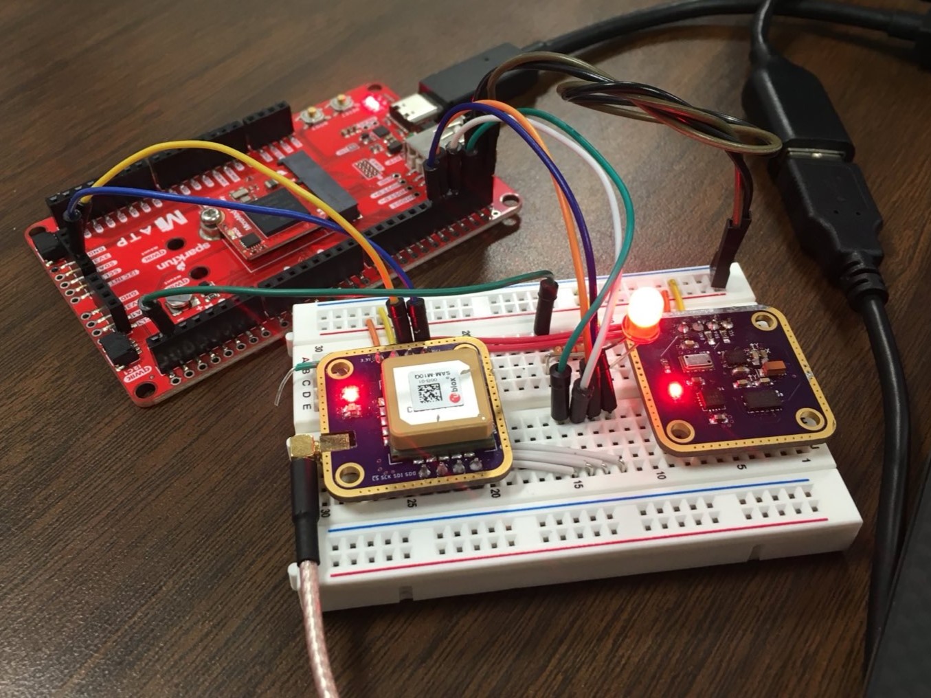
Before the final design of the flight computer was completed, two test boards were created to evaluate the performance of selected sensors and supporting components. The first board, the telemetry board, contained the GNSS and LoRa modules as well as supporting components and the MMCX antenna connector. The second test board, the sensor board, contained the barometer, accelerometers, and magnetometers sensors along with supporting components. These boards were both designed in EAGLE using the same methods and layout principles as the final flight computer design. The boards were fabricated by OSH Park and functioned as expected, allowing for the full flight computer design to continue.
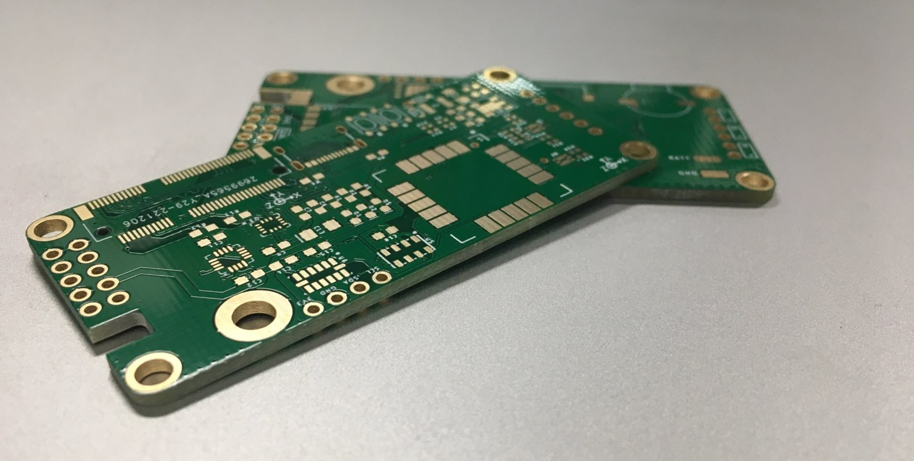
Schematic capture and board layout for the flight computer was completed in Autodesk EAGLE according to manufacturer recommendations as well as lessons learned from previous designs. The physical footprint of the PCB was 1.2” x 2.6” which is a bit longer than the previous Polaris 2 board to accommodate the additional systems. The PCBs were manufactured with ENIG surface treatment to improve solderability issues with fine-pitched components found on previous boards in addition to being recommended by both accelerometer’s manufacturers due to their package footprint.
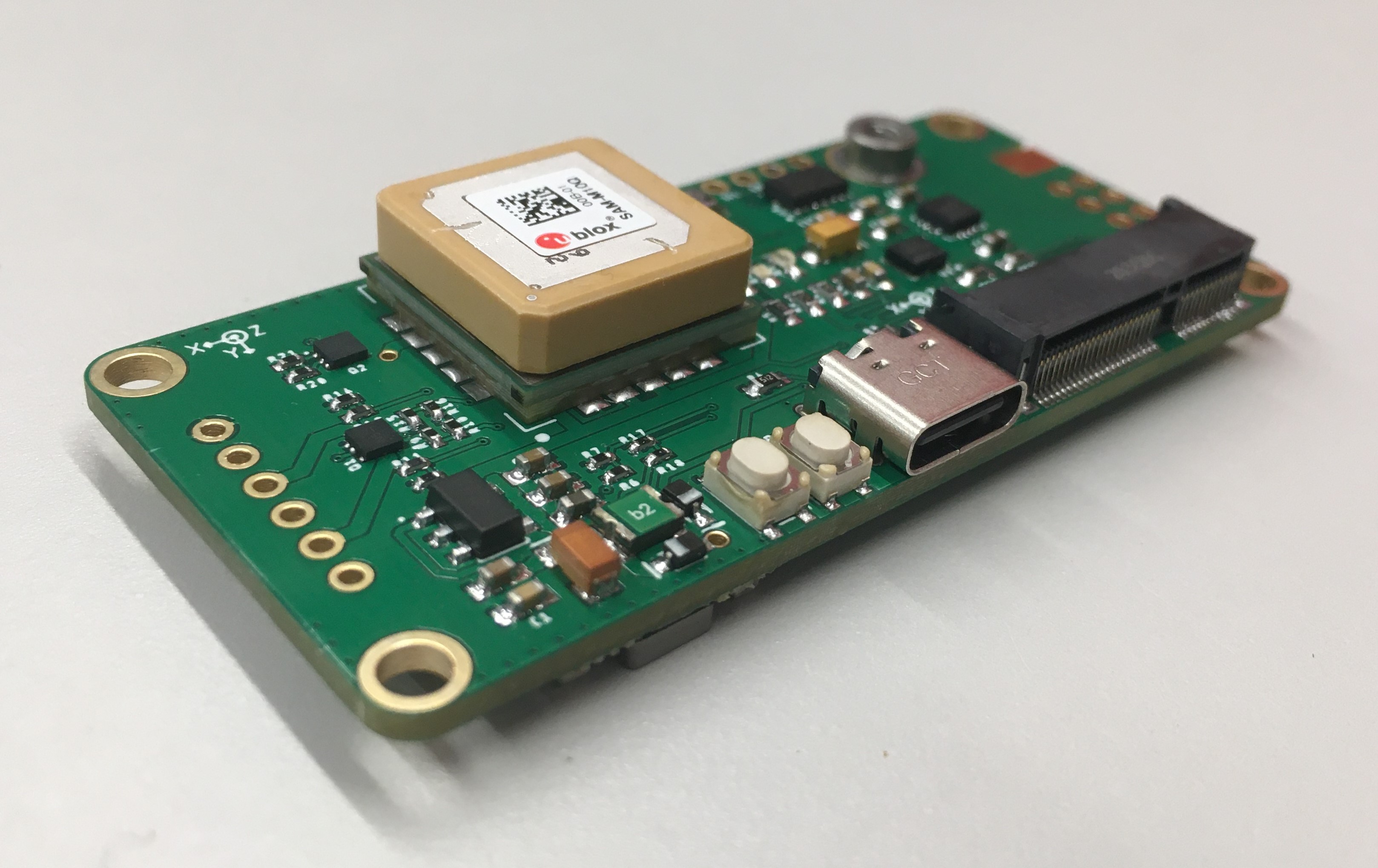
After the boards were received from the manufacturer, they were tested and then assembled with solder paste and SMD components. Once assembled, the flight computer was again tested for continuity to verify no short circuits were created in the assembly process. After a small power issue with an indicator LED was resolved, the board was powered on successfully and programming could be completed with the MicroMod Teensy processer board installed.
Software development for the flight computer included development of a Kalman filter for position and velocity estimation along with a state machine architecture for flight control. Details of the software development can be found in the full technical report. The Kalman filter developed as well as datalogging software was tested before launch using the flight computer attached to a quadcopter. The quadcopter was flown with a similar acceleration profile to that exected during launch and allowed validation and tuning of the Kalman filter’s state estimation.
During post-launch data review, it was found that the state machine malfunctioned and when timing out of the boost state, it cascaded through the other states until reaching the final, ground state. This was caused by improper timeout handling, however the initial timeout itself was caused by an incorrect sign applied to the measured acceleration.
An overview of the development progression of the flight computer can be found below, along with the project’s final report.
08/2022 – 03/2023